Every Industrial Engineer term, in study order
240 terms across 16 phases, in the order the deck teaches them. Each one gets a page you can read in a minute and a quiz that checks whether you did.
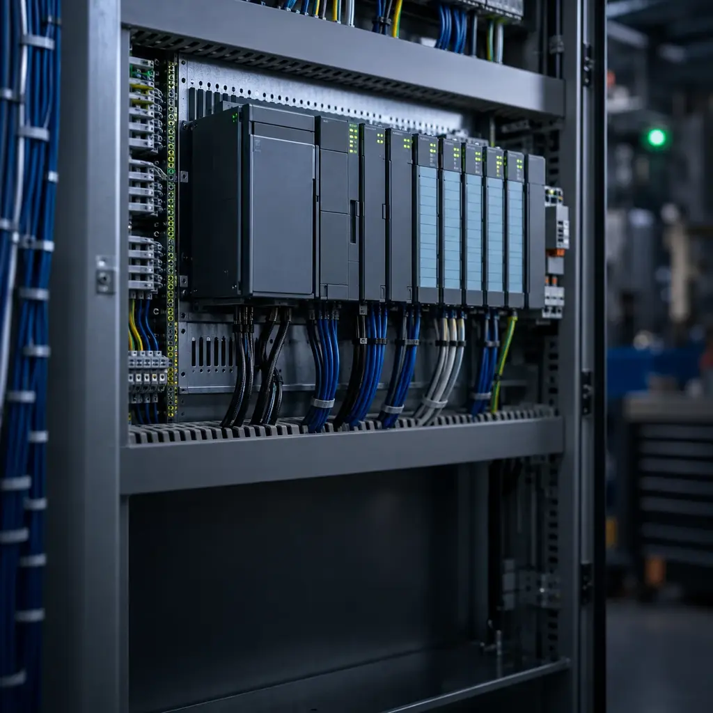
PLC Controller Hardware
Phase 1 · 12 terms
The box itself, from processor and rack to the modules that plug into it, because nothing else in the deck makes sense until you know what a PLC physically is.
- 1 PLC Programmable Logic Controller, an industrial computer that executes deterministic control logic for machines and process...
- 2 CPU / Processor Controller module that executes the user program, manages memory and communications, and coordinates I/O updates.
- 3 Rack / Chassis Mechanical assembly that holds controller modules and connects them through a backplane.
- 4 Backplane Internal bus that distributes power and data between modules in a PLC rack or chassis.
- 5 Power Supply Module that converts incoming plant power to the regulated voltages required by the controller and its modules.
- 6 I/O Module Module that interfaces the PLC with discrete or analog field signals.
- 7 Local I/O I/O installed in the same rack or local assembly as the controller.
- 8 Remote I/O / Expansion I/O installed away from the controller and connected through an industrial network or expansion bus.
- 9 Communication Module Module that adds a network or serial communication interface to the controller.
- 10 Terminal Block Removable or fixed connector where field wiring terminates on an I/O module or base.
- 11 Memory Card Removable storage used for program backup, firmware, recipes, or controller recovery.
- 12 Watchdog Timer Diagnostic timer that faults or resets the controller when program execution exceeds an allowed time or stops responding...
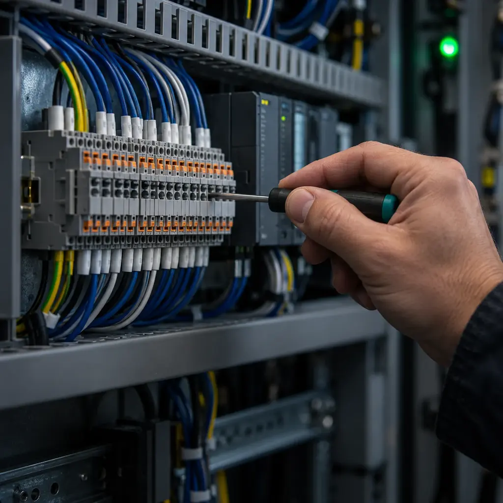
PLC I/O and Field Signals
Phase 2 · 20 terms
Where the controller meets the machine: discrete and analog signals, the wiring conventions behind them, and the field devices that send them.
- 13 DI / Discrete Input On or off input from a field device such as a switch, sensor, or pushbutton.
- 14 DO / Discrete Output On or off output used to command a relay, solenoid, starter, lamp, or other load.
- 15 AI / Analog Input Input that measures a continuous electrical signal such as 4-20 mA, 0-10 V, resistance, or thermocouple voltage.
- 16 AO / Analog Output Output that sends a continuous command signal such as 4-20 mA or 0-10 V to another device.
- 17 Sinking / Sourcing DC circuit convention describing whether a device provides the current return path or supplies current to the load.
- 18 PNP Sensor Three-wire DC sensor whose output sources positive current when active.
- 19 NPN Sensor Three-wire DC sensor whose output sinks current to DC common when active.
- 20 Dry Contact Voltage-free mechanical or solid-state contact that requires an external wetting voltage.
- 21 Wet Contact Contact or output that supplies a voltage when active.
- 22 Two-Wire Transmitter Analog transmitter powered through the same current loop that carries its measurement signal.
- 23 Three-Wire Sensor Powered sensor with separate positive supply, common, and signal conductors.
- 24 4-20 mA Current Loop Analog signaling method in which 4 mA represents the live zero and 20 mA represents full scale.
- 25 0-10 V Signal Voltage-based analog signal whose value is proportional to a configured engineering range.
- 26 Raw Counts Unscaled numeric value produced by an analog converter before conversion to engineering units.
- 27 Scaling Conversion between raw I/O counts and engineering units such as pressure, temperature, or speed.
- 28 Resolution Smallest input or output change an analog module can represent, commonly specified in bits or counts.
- 29 Isolation Electrical separation that limits unwanted current paths between field circuits, channels, and controller electronics.
- 30 Input Filter / Debounce Time or digital filtering used to reject contact bounce and short signal disturbances.
- 31 Fail-Safe State Predetermined output or process condition entered after a detected fault, communication loss, or power loss.
- 32 Normally Open / Normally Closed Contact state defined with the field device in its normal, unactuated, and de-energized condition.

PLC Program Organization and Execution
Phase 3 · 27 terms
How the logic is arranged and how the scan actually runs it, which is the difference between code that works and code that works every time.
- 33 Ladder Diagram (LD) IEC 61131-3 graphical language that represents logic with relay-style contacts, coils, and function blocks.
- 34 Function Block Diagram (FBD) IEC 61131-3 graphical language that connects functions and function blocks with signal lines.
- 35 Structured Text (ST) IEC 61131-3 textual language used for expressions, calculations, loops, and structured control logic.
- 36 Sequential Function Chart (SFC) IEC 61131-3 elements that organize programs and function blocks as steps, actions, and transitions.
- 37 Instruction List (IL, Legacy) Legacy mnemonic PLC language found in older systems but not included in the current IEC 61131-3:2025 language suite.
- 38 Program Top-level user-code organization unit that coordinates control logic and calls routines or function blocks.
- 39 Routine / Function Reusable or callable unit of logic that performs a defined operation.
- 40 Function Block Reusable program unit with defined inputs, outputs, and retained internal state when instantiated.
- 41 Task Execution container that schedules one or more programs by cyclic, periodic, or event-driven rules.
- 42 Continuous / Cyclic Task Task that runs repeatedly whenever higher-priority work and system overhead permit.
- 43 Periodic Task Task scheduled to run at a configured time interval.
- 44 Event Task Task triggered by a configured hardware, motion, network, or program event.
- 45 Scan Cycle Repeated controller operation that services inputs, executes scheduled logic, updates outputs, communicates, and perform...
- 46 Scan Time Elapsed time required for one controller execution cycle or one scheduled task pass.
- 47 First Scan Controller status that is true during the initial logic pass after entering run mode and is used for initialization.
- 48 Rung Horizontal network of conditions and instructions in ladder logic.
- 49 Coil / Contact Ladder elements that write a Boolean result or test a Boolean condition.
- 50 One-Shot / Edge Detection Instruction that becomes true for one execution when a Boolean signal changes state.
- 51 Latch / Unlatch Instructions that set or clear a stored Boolean state until an opposing instruction changes it.
- 52 Interlock Logic that prevents an operation when a condition would make it unsafe or damaging.
- 53 Permissive Condition that must be satisfied before an operation is allowed to start or continue.
- 54 Sequence / State Machine Logic that advances equipment through defined operating states based on commands, conditions, and transitions.
- 55 PID Control Closed-loop control calculation using proportional, integral, and derivative action to regulate a process variable.
- 56 Online Edit Program change made while the controller remains connected and, where supported, continues running.
- 57 Upload Transfer of the current project or data from the controller to the programming workstation.
- 58 Download Transfer of a project, logic, or configuration from the programming workstation to the controller.
- 59 Force Temporary override that commands an I/O point or tag to a selected state for testing and troubleshooting.
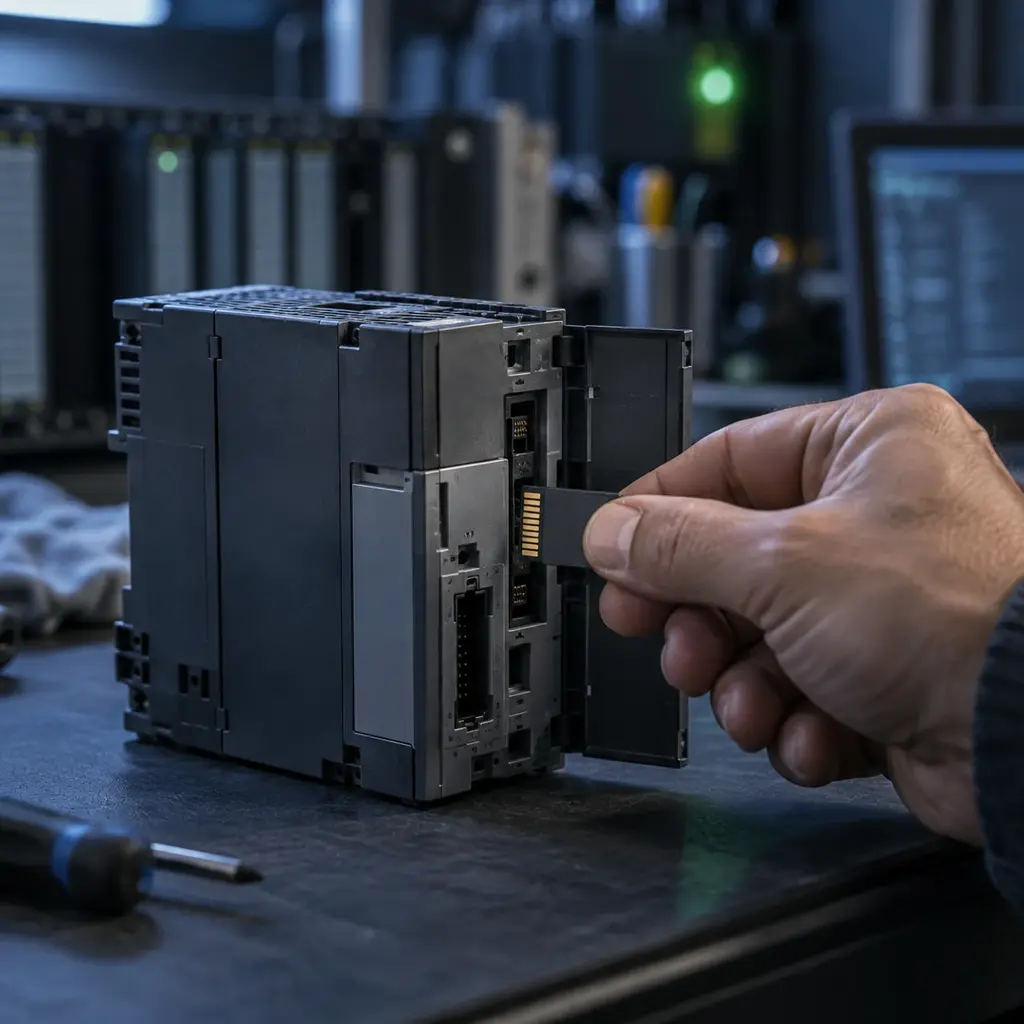
PLC Memory, Tags, and Instructions
Phase 4 · 17 terms
The data a program moves and the instructions that move it, from a single true or false value up to a structured array.
- 60 Tag / Address Symbolic name or numeric location used to reference I/O, memory, or structured data.
- 61 Bit / BOOL Single Boolean value that is either false or true.
- 62 Byte / SINT Eight-bit data quantity, interpreted as bits or as a small integer according to its data type.
- 63 Word / INT / DINT Integer data types or registers commonly represented with 16 or 32 bits.
- 64 REAL / Float Floating-point data type used for fractional values and wide numeric ranges.
- 65 Array Indexed collection of elements that all share the same data type.
- 66 Structure / UDT Grouped data type that combines related members under one name.
- 67 Alias Tag Alternate tag name that references another tag or hardware-defined point.
- 68 Local / Global Tag Tag scoped to one program or made accessible across the controller project.
- 69 Retentive Memory Memory configured to preserve selected values through a power cycle or operating-mode change.
- 70 Nonretentive Memory Memory or instruction state that returns to its defined initial condition after specified resets or power cycles.
- 71 Timer (TON, TOF, TP) IEC timer functions for on-delay, off-delay, and pulse timing.
- 72 Retentive Timer Timer that preserves accumulated time until a reset instruction clears it.
- 73 Counter (CTU, CTD) Functions that count rising events upward or downward and expose completion status.
- 74 Compare Instruction Instruction that evaluates relationships such as equal, not equal, greater than, or less than.
- 75 Move / Copy Instructions that transfer a value or block of data without changing the source.
- 76 Mask Bit pattern used to select which bits participate in a comparison, copy, or logical operation.
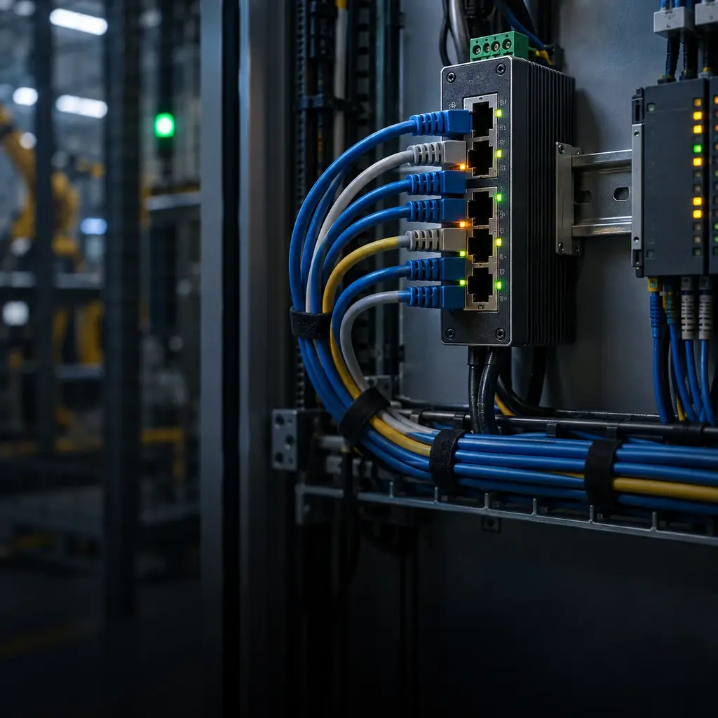
PLC Industrial Communications
Phase 5 · 21 terms
The protocols that let controllers, drives and operator panels talk, plus the addressing and description files that make them agree on what was said.
- 77 EtherNet/IP ODVA industrial Ethernet network that uses the Common Industrial Protocol over standard Ethernet, TCP/IP, and UDP.
- 78 CIP Common Industrial Protocol, the object-oriented application protocol used by EtherNet/IP and other ODVA networks.
- 79 Implicit Messaging CIP communication used for time-critical cyclic I/O data through an established connection.
- 80 Explicit Messaging CIP request-and-response communication used for configuration, diagnostics, and noncyclic data.
- 81 RPI Requested Packet Interval, the configured rate at which a CIP I/O connection requests data updates.
- 82 EDS File Electronic Data Sheet that describes an industrial network device and its configurable attributes.
- 83 PROFINET Industrial Ethernet system maintained by PROFIBUS and PROFINET International for automation communication and real-time...
- 84 PROFIBUS Industrial fieldbus maintained by PROFIBUS and PROFINET International for controller and field-device communication.
- 85 GSD / GSDML File Device-description file used to configure a PROFIBUS or PROFINET device in an engineering system.
- 86 Modbus RTU Modbus protocol encoding commonly carried over RS-485 serial networks.
- 87 Modbus TCP Modbus application protocol transported over TCP/IP Ethernet.
- 88 Coils / Discrete Inputs One-bit read-write and read-only data areas in the Modbus data model.
- 89 Holding / Input Registers Sixteen-bit read-write and read-only data areas in the Modbus data model.
- 90 RS-232 / RS-485 Serial electrical interfaces used for point-to-point or multidrop industrial communication.
- 91 Baud Rate / Parity Serial communication settings that define bit timing and optional error checking and must match at both ends.
- 92 OPC UA Platform-independent industrial communication standard for structured, secure data exchange between systems.
- 93 IP Address / Subnet Mask Network settings that identify an Ethernet device and determine which addresses are locally reachable.
- 94 Default Gateway Router address used to reach devices outside the local IP subnet.
- 95 MAC Address Hardware-layer address assigned to an Ethernet network interface.
- 96 Managed Industrial Switch Ethernet switch with configuration and diagnostic features such as VLANs, port mirroring, redundancy, and traffic priori...
- 97 Device Level Ring (DLR) ODVA ring topology that provides rapid recovery from a single network break on supported EtherNet/IP devices.
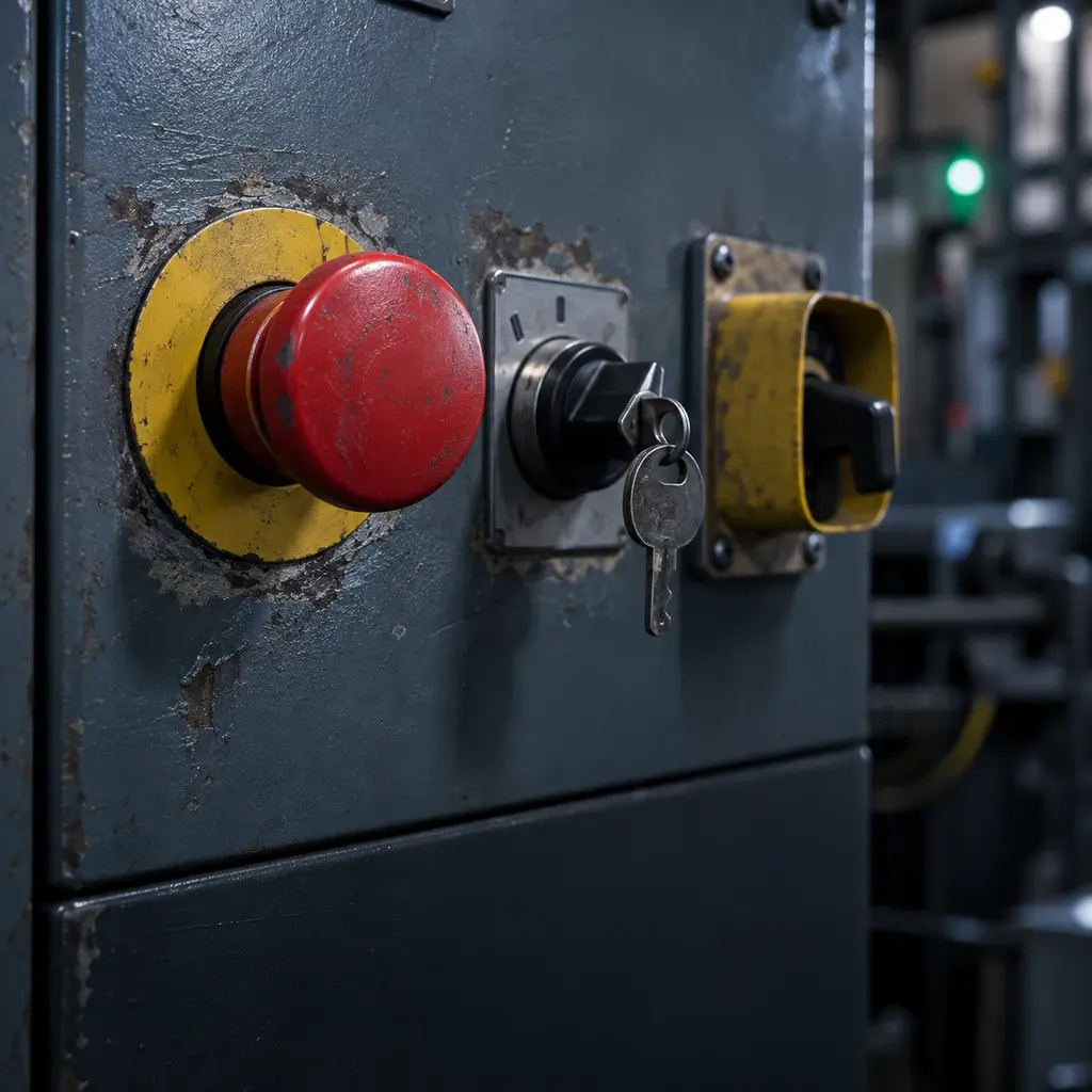
PLC Operating Modes, Safety, and Diagnostics
Phase 6 · 15 terms
Run, program and fault: what a controller does when something goes wrong, and the safety functions that decide how much that costs.
- 98 Run Mode Controller state in which the enabled user program executes and outputs are controlled according to the project.
- 99 Program / Stop Mode Controller state used for editing or maintenance in which normal user logic and outputs are stopped or inhibited accordi...
- 100 Remote Mode Key-switch or controller state that permits operating-mode changes from programming software.
- 101 Major Fault Serious controller or program fault that can stop task execution or place the controller in a faulted state.
- 102 Minor Fault / Warning Diagnostic condition recorded by the controller that may allow logic execution to continue.
- 103 Alarm Reported abnormal condition that requires operator or maintenance attention but does not necessarily stop control.
- 104 Diagnostic Buffer / Fault Log Time-ordered record of controller, module, and network events used for troubleshooting.
- 105 Firmware Vendor-supplied embedded software that defines controller or module behavior and compatibility.
- 106 Safety PLC Controller designed and certified to execute safety-related logic within specified SIL or PL limits.
- 107 SIL Safety Integrity Level, a discrete integrity target for safety functions under IEC 61508 and related sector standards.
- 108 PL Performance Level, a safety-related control-system capability rating under ISO 13849-1.
- 109 Safety Task Protected and monitored controller task used to execute certified safety logic.
- 110 Dual-Channel Input Safety input arrangement using two monitored signal paths to improve fault detection.
- 111 Discrepancy Time Maximum allowed time difference between the expected state changes of paired safety channels.
- 112 Redundancy / Hot Standby Architecture using a synchronized backup controller or component that can assume control after a primary failure.
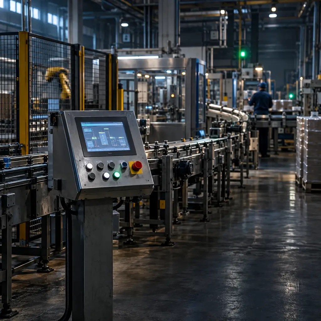
PLC Related Automation Systems
Phase 7 · 6 terms
The neighbors a PLC lives beside on a plant floor, from operator panels and SCADA up to the motion and batch systems it hands work to.
- 113 PAC Programmable Automation Controller, an industry term for a PLC-class controller with broad integration, motion, networki...
- 114 Soft PLC PLC runtime hosted on an industrial computer or virtualized platform instead of dedicated controller hardware.
- 115 HMI Human-Machine Interface used by operators to view status, enter commands, acknowledge alarms, and adjust setpoints.
- 116 SCADA Supervisory Control and Data Acquisition system that monitors and supervises distributed controllers and process equipme...
- 117 RTU Remote Terminal Unit designed to collect field data and control remote assets over telemetry networks.
- 118 DCS Distributed Control System that coordinates process control across networked controllers, operator stations, and enginee...
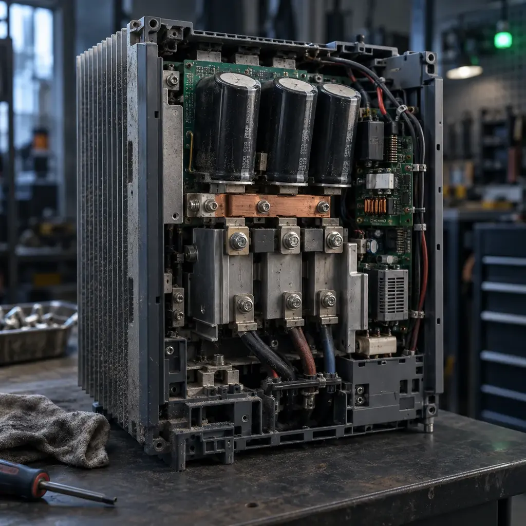
VFD Drive Hardware and Power Path
Phase 8 · 13 terms
Inside the drive: rectifier, DC bus and inverter, the three stages every variable frequency drive uses to rebuild the waveform a motor sees.
- 119 VFD Variable Frequency Drive, an electronic motor controller that varies output frequency and voltage to control AC motor op...
- 120 Converter / Rectifier Input power stage that converts incoming AC to DC, commonly with diodes, thyristors, or active semiconductor switches.
- 121 DC Bus / DC Link Intermediate DC power section between the rectifier and inverter that stores and smooths energy.
- 122 DC Bus Capacitor Capacitor bank that reduces DC-link ripple and supplies short-term energy to the inverter.
- 123 Precharge Circuit Resistor and bypass circuit that limits inrush current while the DC bus capacitors charge at power-up.
- 124 Inverter Output power stage that switches DC into variable-frequency, variable-voltage AC for the motor.
- 125 IGBT Insulated-Gate Bipolar Transistor commonly used as a high-speed power switch in a VFD inverter.
- 126 Braking Chopper Electronic switch that connects a braking resistor to the DC bus when bus voltage rises during deceleration.
- 127 Heat Sink / Cooling Fan Thermal components that remove heat from the drive power electronics.
- 128 Control Board Low-voltage electronics that process commands, feedback, protection, communication, and motor-control algorithms.
- 129 Keypad / HIM Local operator interface used to view status, edit parameters, issue commands, and read faults.
- 130 Control Terminals Low-voltage terminals for digital inputs, analog signals, references, relays, and auxiliary power.
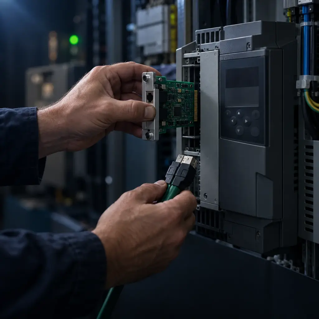
- 131 Communication Option Card Plug-in interface that adds an industrial network or other communication protocol to the drive.
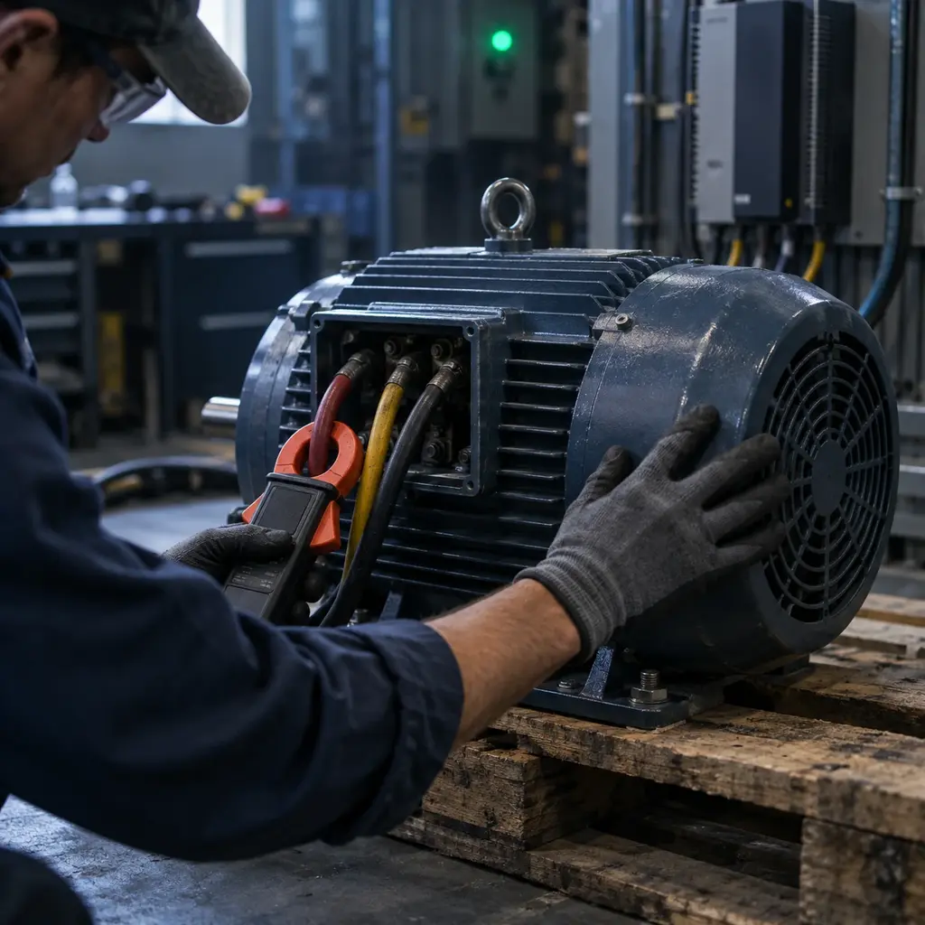
VFD Ratings, Sizing, and Motor Data
Phase 9 · 16 terms
Nameplate arithmetic, where the currents, voltages and duty ratings decide whether a drive can actually run the motor you bolted it to.
- 132 Input Voltage / Phase AC supply voltage and phase configuration for which the drive is designed.
- 133 Output Current Rating Maximum continuous motor current the drive can supply under stated overload and environmental conditions.
- 134 Horsepower / Kilowatt Rating Nominal motor-power class for the drive, secondary to verifying motor current, duty, voltage, and overload requirements.
- 135 Motor Nameplate Voltage Rated motor terminal voltage entered during commissioning so the drive can establish the proper voltage and flux limits.
- 136 Motor Nameplate Current / FLA Rated full-load motor current used by the drive for control, overload modeling, and protection.
- 137 Motor Base Frequency Nameplate frequency at which the motor reaches rated voltage and normally transitions from constant-torque to field-weak...
- 138 Motor Nameplate Speed Rated loaded shaft speed used to estimate slip and improve motor-control accuracy.
- 139 Motor Power Factor Ratio related to real and apparent motor power that may be entered for motor identification or control calculations.
- 140 Motor Efficiency Ratio of mechanical output power to electrical input power at a stated operating point.
- 141 Constant Torque Rating Drive duty rating intended for loads requiring substantial torque across the speed range, commonly with a higher overloa...
- 142 Variable Torque Rating Drive duty rating intended mainly for centrifugal fan and pump loads whose torque demand falls rapidly with speed.
- 143 Overload Rating Permitted output current above the continuous rating for a stated magnitude, duration, and duty cycle.
- 144 SCCR Short-Circuit Current Rating, the maximum prospective fault current an assembly can safely withstand when applied as spe...
- 145 Enclosure Rating NEMA Type or IP code describing the environmental protection provided by the drive enclosure.
- 146 Ambient Temperature Surrounding air-temperature limit used to determine allowable drive loading and cooling requirements.
- 147 Derating Required reduction in drive output capability for conditions such as high temperature, altitude, switching frequency, or...
VFD Electrical and Motor Fundamentals
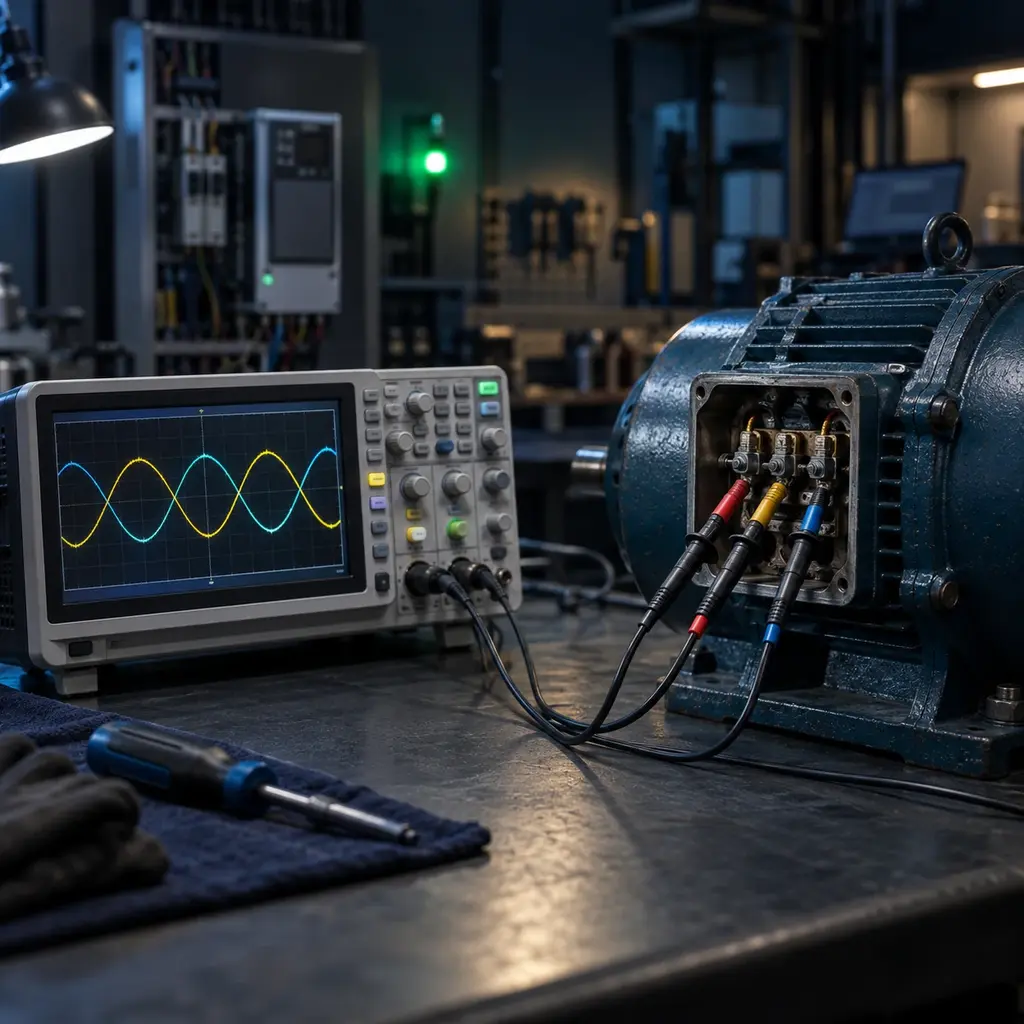
Phase 10 · 14 terms
The physics under the parameters: slip, torque, flux, and the relationship between frequency and voltage that every drive is really controlling.
- 148 V/Hz Ratio Volts-per-hertz relationship used below base speed to maintain suitable motor magnetic flux.
- 149 PWM Pulse-Width Modulation, an inverter switching method that controls effective motor voltage and frequency by varying puls...
- 150 Carrier Frequency Rate at which inverter power devices switch, affecting audible noise, motor heating, cable effects, drive losses, and po...
- 151 Output Frequency Electrical frequency commanded by the drive and applied to the motor.
- 152 Synchronous Speed Rotating magnetic-field speed determined by applied frequency and motor pole count, equal to 120 times hertz divided by...
- 153 Slip Difference between an induction motor's synchronous speed and actual rotor speed.
- 154 Base Speed Approximate motor speed at rated voltage and base frequency.
- 155 Field Weakening Operation above base frequency where voltage cannot rise proportionally, reducing available torque as speed increases.
- 156 Constant Torque Region Operating range, usually at or below base speed, in which rated motor flux allows approximately constant torque.
- 157 Constant Horsepower Region Operating range above base speed where available torque falls approximately as speed rises while power remains roughly c...
- 158 DC Bus Voltage Voltage on the DC link, typically near 1.35 to 1.41 times the AC line-to-line RMS voltage depending on rectifier topolog...
- 159 RMS Root-mean-square value used to express the heating-equivalent magnitude of an AC voltage or current.
- 160 Regeneration Power flow from the rotating motor and load back into the drive DC bus during overhauling or decelerating conditions.
- 161 Four-Quadrant Operation Capability to produce motoring and braking torque in both forward and reverse directions.
VFD Control Modes and Tuning
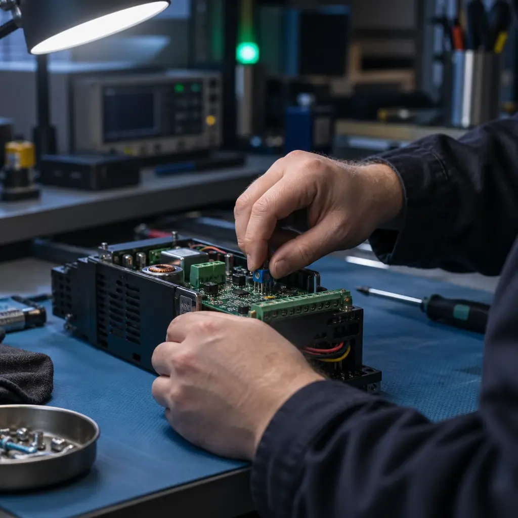
Phase 11 · 15 terms
How a drive decides what to send the motor, from plain volts per hertz up to closed loop vector control, and how each mode is tuned.
- 162 Open-Loop Control Motor control without direct shaft-speed or position feedback from an encoder.
- 163 Closed-Loop Control Motor control that uses encoder or resolver feedback to regulate shaft speed, torque, or position.
- 164 Scalar / V/Hz Control Control method that commands motor voltage mainly as a function of output frequency without independently regulating flu...
- 165 Sensorless Vector Control Control method that estimates motor flux, speed, or torque from electrical measurements and a motor model without an enc...
- 166 Flux Vector Control Vector method that independently regulates torque-producing and flux-producing current components for improved dynamic a...
- 167 Torque Control Operating mode in which motor torque is the primary commanded variable or regulated limit.
- 168 Speed Control Operating mode in which motor speed or frequency is the primary regulated variable.
- 169 Autotune / Motor Identification Commissioning routine that measures or estimates motor parameters used by the drive's control model.
- 170 Slip Compensation Automatic frequency adjustment that reduces induction-motor speed change as load torque changes.
- 171 Torque Boost Additional low-frequency voltage used to compensate stator resistance and improve starting or low-speed torque.
- 172 Current Limit Control function that restricts motor current and may reduce acceleration or output frequency to avoid an overcurrent tr...
- 173 Stall Prevention Drive response that modifies acceleration, deceleration, or speed to keep current or DC-bus voltage within limits.
- 174 Flying Start / Catch on the Fly Function that detects the speed and direction of a spinning motor before smoothly taking control.
- 175 Skip Frequency Configured speed band the drive avoids during steady operation to reduce mechanical resonance.
- 176 Internal PID Drive-based proportional-integral-derivative controller that adjusts motor speed to regulate process feedback.
VFD Commands, References, and Stopping
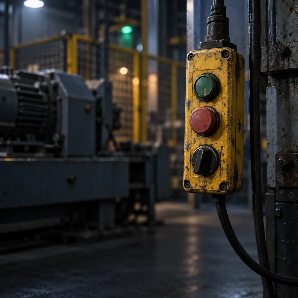
Phase 12 · 18 terms
Starting, referencing and stopping, including the several very different things a drive can mean by the word stop.
- 177 Run Command Signal or network command that requests the drive to operate when all enables and permissives are satisfied.
- 178 Run Enable Hardware or logic condition that must be present before the drive will accept a run command.
- 179 Forward / Reverse Direction command that selects the sign of motor rotation subject to configuration and interlocks.
- 180 Speed Reference Commanded speed or frequency value received from the keypad, analog input, preset, PID, or network.
- 181 Minimum / Maximum Frequency Configured lower and upper limits applied to the commanded drive output frequency.
- 182 Acceleration Time Configured time for the drive to ramp between defined low and high frequency reference points.
- 183 Deceleration Time Configured time for the drive to ramp between defined high and low frequency reference points.
- 184 S-Curve Ramp profile that rounds acceleration changes to reduce mechanical shock and jerk.
- 185 Jog Temporary command that runs the motor at a dedicated low speed for setup or positioning.
- 186 Ramp Stop Stop method that reduces commanded frequency along a programmed deceleration ramp.
- 187 Coast Stop Stop method that disables inverter output and lets the motor slow according to load inertia and friction.
- 188 DC Injection Braking Stopping or holding method that applies DC current to the motor stator to create braking torque without regeneration.
- 189 Dynamic Braking Method that dissipates regenerated motor energy in a resistor connected to the DC bus through a braking chopper.
- 190 Braking Resistor Resistor sized to absorb regenerated energy and limit DC-bus voltage during dynamic braking.
- 191 Two-Wire Control Maintained-contact control scheme in which the run input remains asserted while operation is requested.
- 192 Three-Wire Control Momentary start and stop control scheme with drive logic that seals in the run state.
- 193 Local / Remote Selection between commands and references from the drive interface and those from external terminals or communications.
- 194 Preset Speed Stored frequency or speed reference selected by digital inputs or network commands.
VFD Power Quality, Wiring, and Motor Protection
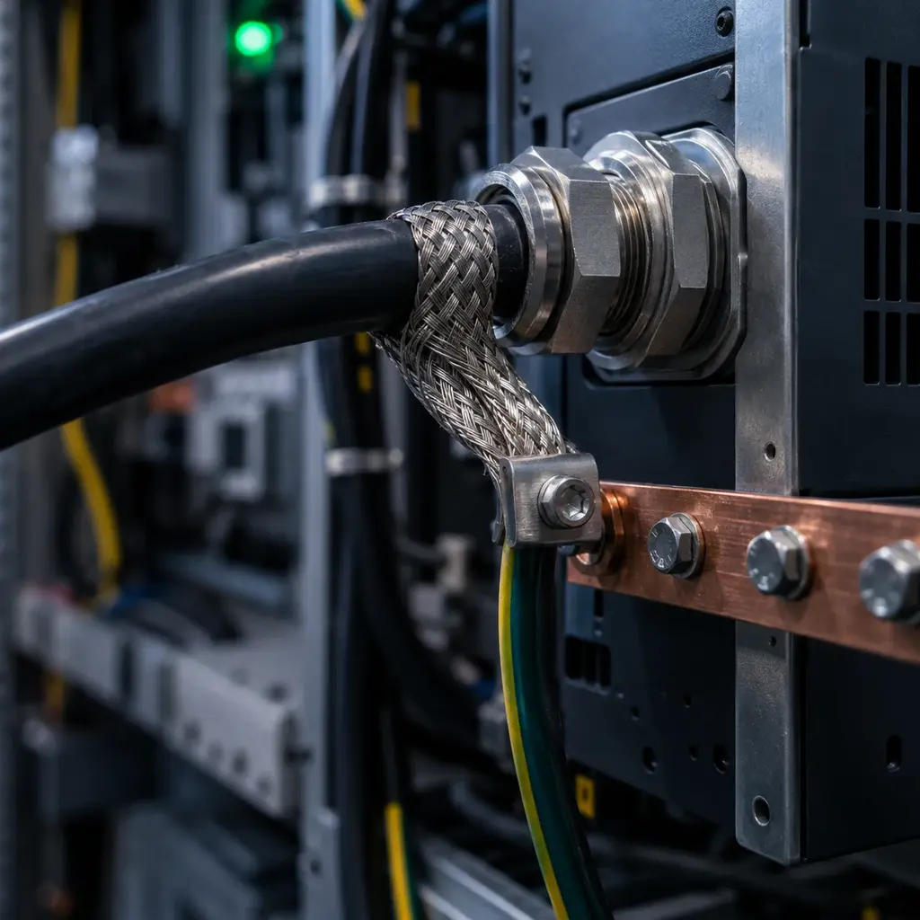
Phase 13 · 18 terms
Harmonics, reflected waves, shielded cable and bearing currents: the side effects a drive inflicts on everything around it.
- 195 Harmonics Current or voltage components at integer multiples of the fundamental frequency that distort the supply waveform.
- 196 THD Total Harmonic Distortion, a ratio that summarizes harmonic content relative to the fundamental component.
- 197 Six-Pulse Rectifier Common three-phase diode bridge with six switching pulses per line cycle and characteristic input-current harmonics.
- 198 Twelve-Pulse / Eighteen-Pulse Drive Multipulse rectifier arrangement using phase-shifted transformer windings to reduce selected line harmonics.
- 199 Active Front End (AFE) Controlled rectifier that can regulate the DC bus, reduce line-current distortion, and often return regenerated power to...
- 200 Line Reactor Series input inductor that reduces current peaks, line disturbances, and some harmonic current while adding impedance.
- 201 DC Link Choke Inductor in the DC link used to smooth current and reduce stress and line harmonics.
- 202 Load Reactor Series output inductor that reduces motor current rise, voltage stress, and some long-cable effects.
- 203 DV/dt Filter Output filter that reduces the rate of voltage change and peak motor-terminal voltage from PWM switching.
- 204 Sine-Wave Filter Output filter that converts the PWM waveform toward a sinusoidal motor voltage.
- 205 Reflected Wave Cable-transmission effect that can produce high motor-terminal voltage peaks when PWM pulses reflect on long leads.
- 206 Common-Mode Voltage Voltage shared by motor phases relative to ground that can drive leakage and bearing currents.
- 207 Bearing Current Unwanted current through motor bearings caused by common-mode voltage, shaft voltage, or grounding paths.
- 208 Shaft Grounding Ring Conductive device that provides a low-impedance path from the motor shaft to frame to reduce bearing discharge damage.
- 209 Shielded VFD Cable Motor cable designed with suitable insulation and a continuous low-impedance shield or armor for PWM drive service.
- 210 Bonding Low-impedance connection of drive, enclosure, cable shield, and motor frame to control fault and high-frequency currents...
- 211 Output Contactor Contactor between drive and motor that must be applied and sequenced only as permitted by the drive manufacturer.
- 212 Bypass Power and control arrangement that allows a motor to operate across the line when the drive is isolated or unavailable.
VFD Safety, Faults, and Diagnostics
Phase 14 · 14 terms
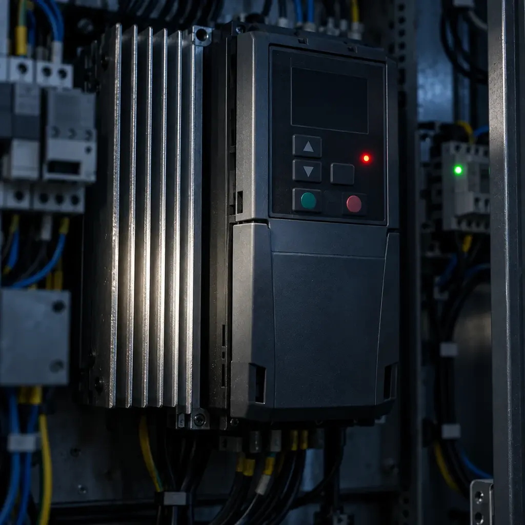
What a drive does when it trips, what the fault codes are telling you, and how safe torque off stops the motor without killing the panel.
- 213 STO Safe Torque Off, a certified drive safety function that prevents torque-producing energy without serving as electrical i...
- 214 Motor Electronic Overload Drive thermal model that estimates motor heating from current, speed, time, and configured motor data.
- 215 Overcurrent Fault Trip caused when output current exceeds the drive's instantaneous protection threshold.
- 216 DC Bus Overvoltage Trip caused when DC-link voltage rises above its safe limit, often during rapid deceleration or high line voltage.
- 217 DC Bus Undervoltage Trip or warning caused when DC-link voltage falls below the level needed for reliable operation.
- 218 Ground Fault Detected unintended current path from a drive output or motor circuit to ground.
- 219 Input Phase Loss Loss or severe imbalance of an incoming AC phase that increases rectifier and DC-bus stress.
- 220 Output Phase Loss Detected open motor phase or severe output-current imbalance between phases.
- 221 Overtemperature Trip caused when measured drive, heat-sink, or motor temperature exceeds a configured safe limit.
- 222 Motor Thermistor / PTC Temperature-sensitive device embedded in a motor and connected to the drive or protection relay.
- 223 Fault Protective condition that normally stops or inhibits drive output and requires the cause to clear before reset.
- 224 Alarm / Warning Abnormal condition reported by the drive that may allow continued operation for a limited or indefinite time.
- 225 Fault History Stored record of recent trips and operating data used to identify recurring causes.
- 226 Auto Restart Configured function that attempts to resume operation after selected faults and must be evaluated for machine safety.
VFD Parameters and Communications
Phase 15 · 6 terms
The parameter set itself, and the network words a controller uses to read and write it while the machine is running.
- 227 Parameter Stored drive setting that defines ratings, control behavior, I/O functions, limits, or communications.
- 228 Parameter Group Vendor-defined category used to organize related drive settings.
- 229 Application Macro Preset group of parameter assignments for a common control arrangement or machine application.
- 230 Control Word / Status Word Bit-mapped network command and feedback data used to control and monitor a drive.
- 231 Reference / Feedback Word Network data values used to send a speed or torque command and return actual operating feedback.
- 232 Modbus RTU / Modbus TCP Register-based serial or Ethernet protocols commonly used to command, monitor, and configure drives.
VFD Related Drive Terms
Phase 16 · 8 terms
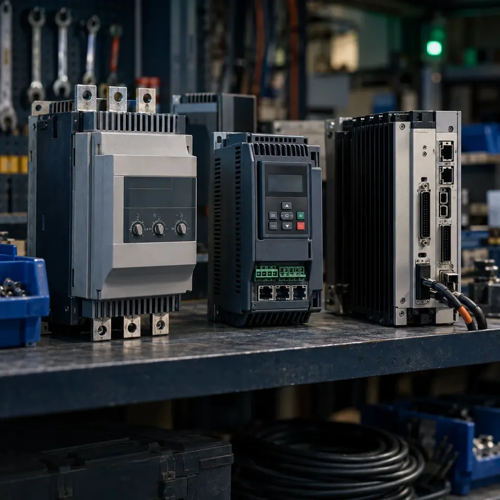
The drive family's wider vocabulary, from soft starters and servo drives to the regenerative units people also call a drive.
- 233 VSD Variable Speed Drive, a broad term for equipment that controls prime-mover or motor speed.
- 234 ASD Adjustable Speed Drive, another broad term for a motor-speed control system.
- 235 VVVF Variable Voltage Variable Frequency, a descriptive term for a common AC drive output method.
- 236 AC Drive Common industry name for an electronic drive that controls an AC motor.
- 237 Soft Starter Solid-state starter that limits motor starting voltage and current but does not provide continuous variable-frequency sp...
- 238 Inverter-Duty Motor Motor designed or rated to tolerate specified PWM voltage stress, thermal conditions, and operating-speed range.
- 239 Regenerative Drive Drive capable of returning braking energy from the DC bus to the AC supply.
- 240 Common DC Bus Architecture in which multiple drive sections share one DC link so energy can be exchanged between axes or supplied by a...